Introduction
Connected-Diagrams is a diagram editor that allows you to connect your diagrams together, embed links to other diagrams or sub-diagrams within a diagram and seamlessly traverse those links.
Before reading through this manual it is highly recommended that you run through the tutorial which will introduce you to the basics of the editor.
Many features in this documentation are presented as question/answers so reading those will help you become proficient with connected-diagrams.
The basic concepts and terminology used throughout are introduced below.
node
A box/shape with an optional description.
Tip
Create a new node by double clicking in any space.
Create a shaped node by dragging a shape from the left side panel.
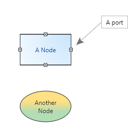
Lines can be connected to a node such that the end of the line will move with the node. These connection points are called ports and are shown below.

There are various visual elements to a Node including how to layout the optional text within the Node. These include
- Colours (background/line/text)
- Optional fill (gradient or solid)
- Border line options (thickness, line type)
- Text margins : the space around the text in the Node
- Text bounds : where the text is placed relative to the center of the Node and its width and height. e.g. 0.5 equates to the right edge of the Node, i.e. the center + half of the width.
line
A line optionally from or to a node with optional visible ends (e.g. arrows).
port
A connection point on a node for a line to connect to. Belongs to a node, allows many lines to connect in/out from it.
FAQ
Question: How do I create a line between two boxes or nodes?
When you move the mouse towards a box/node then existing ports for that node will appear.
Once you move the cursor near to an existing port, it shows as highlighted then you can click-and-drag to create a line starting from that port.
Drag the line either to another port, or to anywhere on the diagram to leave the end floating at that position.
Note that if you stop moving the cursor for a while, then the available ports will fade out. To see them again simply move the cursor.
Question: No ports appear when I move the cursor near to a node?
If no ports appear then you very likely have something selected (a node or a line).
To clear the selection press escape or click on any free space in the diagram.
Ports should then appear.
Question: No ports appear on a box or node and I have nothing selected, why?
Either:
- You are able to delete ports so it is possible that there are no ports attached to that node.
If this is the case then you can right click on the box/node to add a new port using
 and click where you wish the port to be created. This is a relative position to the position of the node, so the port will move with the node.
 - The node has ports-disabled, right click on the box/node to re-enable them.

grouped nodes
Multiple nodes can be grouped together. Once grouped node properties cannot be edited,
although the text within each node can still be edited by double clicking on that node.
Use the icons to group/ungroup selected nodes:
![]()
![]()
remote diagram nodes
A node visible in the current diagram that represents another diagram. By default, this is indicated by a visible highlight which also indicates what type of remote connection is present:
- remote-to-unknown : The node is representing another diagram, but this diagram may not exist or is unknown at present.
- remote-known : The node is representing another specified diagram. If you double-click on this node it will take you to that diagram 1.
- sub-diagram : The node represents a sub-diagram of this diagram. If you double-click on this node it will take you to the sub-diagram 1.

These types of links can be set by right-clicking on a node and chosing one of

To specify a remote-to-unknown choose the Link to Diagram option and then choose the button at the top called

diagram
A diagram is a collection of nodes, ports and lines. It can contain references (using nodes) to other diagrams.
Export as Image
Once you have your diagram as you wish you can export a snapshot of it as an image. Simply choose the zoom-level that you want the diagram to be rendered at
then choose the file menu  / Export Image, enter a filename to save.
A png (a very common image file type) will be saved of the entire diagram at the visual zoom level that you pre-selected.
tags
Diagrams are indexed using tags. Tags are separated by spaces. This means that you can mark a diagram with multiple aspects and search across those aspects when opening such a diagram. These tags can be edited directly from the Open diagram window. When you change a tag the text will go red until you submit (press enter) to save.
Note: When searching for a tag you must enter the entire tag name. So if you have tagged a diagram with "simple", you will not find it by entering "sim".
Tip
If only a single diagram is found after filtering in the Open diagram window then you can simply press enter to open it.